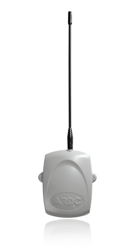
VHF
Transmitters
Range of VHF Radio Transmitters
- 5 or 9 Hardwired input models
- Serial connection models
- Limited Contact ID models
- New chassis design
- New slip whip antenna
- Programmable alarm input delay
- Programmable periodic test intervals
- Programmable positive or negative trip
- Engineer test button
Features
- Field programmable features for on-site convenience.
- Synthesized design.
- Engineer test button – for easy on-site testing.
- Low battery reporting.
- Battery restore reporting
- All inputs may be programmed individually for positive or negative trip making the transmitter compatible with any control panel.
- Power-up signal transmission after re-boot indicating possible willful tamper condition.
- Programmable mains fail/restore signal delays from 15 to 250 minutes.
- After power up, a 5 minute test window is available for the Technician to test mains fail/restore without delays.
- Random transmission delay for mains fail/restore events thus reducing the possibility of signal clashes during area power outages.
- Signal buffering is used when inputs are triggered simultaneously. Signals are stored in the transmitter and sent in event order.
- Manufactured using the latest surface mounting techniques which minimizes the chances of human error.
- The transmitter draws low current on standby placing minimal strain on the system battery.
- On board LED indicates seven different transmitter conditions for fast and simple diagnostics.
Transmitter Specifications – TX 790C Range
|
Frequency Range |
132 - 174 MHz |
Transmitter Specifications – TX 790C Range
Models |
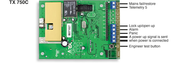
TX 750C Reports a 4 digit code number and 11 telemetry conditions: • open/close • panic • alarm • battery low/ restore • self-test • engineer test • telemetry 5 • dedicated mains fail/restore |
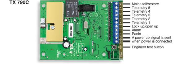
TX 790C Reports a 4 digit code number and 15 telemetry conditions: • open/close • panic • alarm • battery low/ restore • self-test • engineer test • telemetry 1 • telemetry 2 • telemetry 3 • telemetry 4 • telemetry 5 • dedicated mains fail/restore |
||
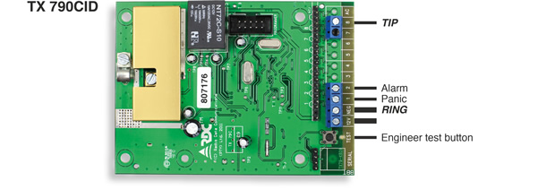
| TX 790CID Reports a 4 digit code number, Contact ID and 2 hardwired telemetry conditions: • panic • alarm • TIP • RING Limited Contact ID interface support: Up to 4 partitions are supported / reported Up to 31 zones reported (zone 32 reserved for universal or unknown zone) Up to 15 users / key holders reported (user 16 reserved for universal or unknown user) |
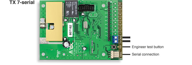
TX 790 Serial Reports a 4 digit code number and Limited Contact ID Serial interface support: Up to 4 partitions are supported / reported Up to 31 zones reported (zone 32 reserved for universal or unknown zone) Up to 15 users / key holders reported (user 16 reserved for universal or unknown user) |
Operation
- Low battery and restore reporting.
- Self test programmable between 1-250 hours.
- Internal pull-up resistors for negative trip eliminates the need for external resistors.
- A power-up signal is sent which can indicate that the transmitter has been tampered with by an insider.
- A programmable mains fail/restore delay can be set from 15 – 250 minutes plus a random delay to prevent signal clashing. The factory default is 15 minutes plus the random delay. The installer, however, is able to test mains fail/restore signals without delay for thirty minutes after the installation.
- Engineer test button.
- Signal buffering – when inputs are triggered simultaneously they are stored in the transmitter and sent in priority order.
- LED indicates 7 different transmitter conditions.
